Diaphragm Coupling For Turbine

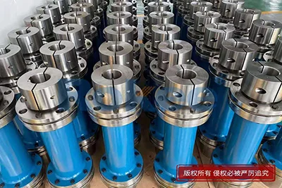
Diaphragm couplings have emerged as a core transmission component tailored for turbine systems, serving as a critical connecting medium between turbine driving shafts and driven mechanical equipment. As high-speed rotating machinery, turbines operate under extreme working conditions characterized by high rotational speeds, continuous load changes, and complex vibration interference, which place stringent demands on the stability, flexibility, and durability of connecting couplings. Unlike traditional rigid and elastic couplings, diaphragm couplings rely on the elastic deformation of precision metal diaphragm components to achieve torque transmission and shaft misalignment compensation, combining high transmission efficiency with excellent adaptive performance. They effectively address common operational problems of turbine systems, including axial displacement, angular deviation, and parallel misalignment between connected shafts caused by thermal expansion, mechanical vibration, and installation errors. With outstanding fatigue resistance, lubrication-free operation, and low vibration characteristics, these couplings have become the preferred choice for various industrial turbine equipment, ensuring long-term stable and efficient operation of turbine transmission systems while reducing mechanical failure risks and operational interference.
The basic structural composition and working mechanism of diaphragm couplings lay a solid foundation for their superior performance in turbine system applications. The overall structure of a turbine diaphragm coupling is compact and streamlined, mainly composed of precision-processed metal diaphragms, connecting hubs, fastening bolts, and spacing sleeves, with no redundant transmission accessories or vulnerable elastic rubber parts. The core functional component is the thin metal diaphragm group, which adopts optimized cutting and forming processes to achieve uniform stress distribution and controllable elastic deformation. During turbine operation, the driving torque generated by the turbine rotor is transmitted from the input shaft hub to the diaphragm group through evenly arranged fastening bolts, and the elastic deformation of the diaphragms converts discrete mechanical power into continuous and stable torque output to the driven shaft. When the turbine system produces shaft misalignment due to thermal deformation after long-time high-temperature operation or minor installation deviations, the metal diaphragms can produce reversible micro elastic deformation to compensate for axial, angular, and radial displacement errors in real time. This flexible compensation mode avoids rigid stress accumulation between shafts, eliminates additional mechanical load on turbine bearings and rotors, and maintains zero-loss torque transmission without interfering with the normal rotation rhythm of high-speed turbine equipment.
The unique performance advantages of diaphragm couplings make them highly compatible with the extreme operating characteristics of turbine equipment. Turbines often run continuously for thousands of hours under high-speed and high-load conditions, and traditional couplings are prone to aging, deformation, and transmission failure under such working environments, while metal diaphragm couplings break through the limitations of traditional coupling structures and materials. First of all, they feature completely lubrication-free operation, eliminating the hidden troubles of oil leakage, lubricant deterioration, and regular oil replacement that plague gear and chain couplings, which is particularly critical for closed and high-temperature turbine operating environments. Secondly, the integral metal diaphragm structure has excellent high-temperature resistance and corrosion resistance, which can adapt to the high-temperature flue gas and humid industrial atmosphere around turbine units without performance attenuation or structural oxidation damage. In addition, the uniform stress design of the diaphragm enables it to withstand frequent cyclic load impacts during turbine start-up, shutdown, and load switching, effectively resisting fatigue cracks and structural damage. Meanwhile, the coupling has extremely low vibration and noise transmission characteristics, which can suppress the resonance phenomenon easily generated by high-speed rotation of turbine shafts, stabilize the overall operation balance of the unit, and greatly extend the service life of turbine transmission components.
Diaphragm couplings play an irreplaceable role in improving the operational stability and safety of turbine systems. In the actual operation of industrial turbines, tiny shaft misalignments are inevitable due to equipment aging, foundation settlement, thermal expansion and contraction, and long-term mechanical vibration. These subtle deviations will be continuously amplified with high-speed rotation, triggering problems such as increased bearing wear, shaft vibration overload, and seal failure, and even leading to sudden shutdown accidents in severe cases. Diaphragm couplings rely on the precise elastic compensation capability of metal diaphragms to absorb various shaft displacement deviations in real time, constrain shaft runout within a safe range, and avoid concentrated impact stress on key turbine components. Moreover, the rigid torque transmission characteristic of the coupling ensures zero phase difference in power transmission, maintaining the precise power output accuracy required by turbine power generation and mechanical drive systems. When the turbine encounters sudden load fluctuations or short-term impact loads, the diaphragm structure can buffer and disperse instantaneous peak stress, preventing rigid torque impact from damaging the turbine rotor and precision transmission parts. This stable protection mechanism effectively reduces the failure rate of turbine units and improves the overall operational safety coefficient of mechanical systems.
The material selection and precision manufacturing process of turbine diaphragm couplings determine their long-term service performance and reliability. The metal diaphragms used for turbine-specific couplings are made of high-strength alloy materials with excellent fatigue resistance and mechanical stability, which undergo strict heat treatment and surface strengthening processes to eliminate internal material stress and improve structural toughness and wear resistance. Different from ordinary mechanical couplings, turbine diaphragm components are processed by high-precision numerical cutting and grinding technology to ensure consistent thickness, uniform texture, and accurate geometric dimensions of each diaphragm, so as to guarantee consistent elastic deformation performance of the entire diaphragm group during operation. The matching hubs and fastening parts are also made of high-rigidity metal materials to avoid structural deformation and bolt loosening under long-term high-speed operation. The integrated assembly design avoids accumulated errors caused by multi-component matching, ensuring the overall structural rigidity and dynamic balance of the coupling. After manufacturing, each coupling will undergo strict dynamic balance testing and stress fatigue testing to verify its adaptability to high-speed turbine operating conditions. This rigorous material matching and manufacturing process enables diaphragm couplings to maintain stable mechanical performance during long-cycle uninterrupted operation, meeting the high-reliability operation requirements of turbine equipment.
The installation and commissioning specifications of diaphragm couplings are key links to maximize their performance in turbine systems. Although diaphragm couplings have strong misalignment compensation capability, standardized installation and debugging are still essential to avoid excessive deviation exceeding the compensation range and affecting service life. Before installation, all matching shaft ends, hubs, and diaphragm components need to be thoroughly cleaned to remove impurities such as rust, oil stains, and metal debris that may affect assembly accuracy. During the assembly process, operators need to ensure the coaxiality of the driving and driven shafts, control the installation gap and parallelism of the two shafts within a reasonable range, and evenly fasten the connecting bolts in a fixed sequence to avoid uneven stress on the diaphragm group caused by asymmetric fastening. After preliminary installation, professional precision detection tools are required to calibrate shaft misalignment, correct tiny installation deviations, and ensure that the coupling can give full play to elastic compensation advantages during operation. In the commissioning stage, low-speed trial operation is carried out first to observe the vibration, noise and temperature changes of the coupling and turbine shaft system, and then the load and speed are gradually increased to complete the overall commissioning. Standardized installation and commissioning can not only avoid early fatigue damage of couplings but also optimize the dynamic operation state of the entire turbine transmission system.
Scientific daily maintenance and fault monitoring can effectively extend the service life of diaphragm couplings for turbines and maintain long-term stable operation. Compared with other types of couplings, diaphragm couplings have extremely low maintenance costs and simple maintenance procedures due to their lubrication-free and non-wearing structural characteristics. Daily maintenance mainly focuses on regular visual inspection and operating state monitoring, including checking whether the diaphragm surface has micro cracks, deformation or corrosion marks, and confirming whether the fastening bolts have loosened or displaced under long-term vibration. During the regular shutdown maintenance of turbine units, professional testing equipment can be used to detect the fatigue degree and elastic performance of the diaphragm group, and eliminate potential structural hidden dangers in advance. In terms of fault monitoring, staff can judge the operating state of the coupling in real time through the vibration amplitude, operating noise and temperature change data of the turbine shaft system. Abnormal vibration and temperature rise often indicate excessive shaft misalignment or diaphragm fatigue failure, which requires timely shutdown inspection and correction. Reasonable maintenance cycles and standardized monitoring methods can avoid sudden failure of couplings, reduce unplanned shutdown time of turbine equipment, and improve the continuous operation efficiency of industrial production systems.
With the continuous upgrading of turbine equipment towards high speed, high power and high efficiency, the technical optimization and application prospects of diaphragm couplings are becoming increasingly broad. Modern industrial turbines have higher requirements for transmission accuracy, operational stability and service life, which continuously promote the iterative upgrading of diaphragm coupling design and manufacturing technology. At present, the structural design of diaphragm couplings is developing towards lightweight and high-strength integration, with optimized diaphragm arc transition and cutting structure to further improve misalignment compensation ability and fatigue resistance while reducing overall structural weight. The application of new high-temperature resistant and high-strength alloy materials further enhances the adaptability of couplings to extreme turbine working conditions. In addition, combined with intelligent monitoring technology, diaphragm couplings can realize real-time collection and analysis of operating stress, vibration and displacement data, providing data support for predictive maintenance of turbine equipment. As a key supporting component of turbine systems, diaphragm couplings will continue to play an irreplaceable role in energy, power, industrial manufacturing and other fields, and continuously adapt to the development needs of high-end turbine mechanical equipment with technological innovation.




Links:
- Calibration Weight
- Digital Viscometer
- Carpas Industriales
- Exhibition Tent
- Industrial Cardan Shaft
- PU Sandwich Panel Machine
- PIR Sandwich Panel Line
- Sandwich Panel Machine
- Sandwich Panel Production Line
- PU Sandwich Panel Line
- Sandwich Panel Line
- Flexible Couplings Manufacturer In China
- Elastic Couplings Manufacturer In China