Flexible Shaft Coupler For Motor Shaft

A flexible shaft coupler for motor shaft serves as a fundamental connecting component in rotary power transmission systems, bridging the output end of an electric motor and the input shaft of driven equipment to transfer rotational torque while accommodating minor physical deviations between the two shafts. Unlike rigid couplers that lock shafts into a perfectly fixed alignment and pass all mechanical stress directly onto motor bearings and load assemblies, flexible variants rely on elastic deformation to isolate harmful forces that arise during normal operation. Even when technicians carefully align shafts during assembly, perfect alignment is rarely sustained once the machine starts running. Thermal expansion from motor heat, slight structural settling of mounting frames, and dynamic deflection under operating loads all create small shifts between shaft centers. Without a flexible coupler, these misalignments generate persistent cyclic stress on motor bearings, shaft seals, and internal windings, accelerating wear and triggering premature failure. The core design concept centers on controlled flexibility: the coupler maintains reliable torque transmission while allowing limited angular, parallel radial, and axial movement between mating shafts. This simple mechanical principle protects expensive motor assemblies and downstream machinery by absorbing displacement rather than resisting it. Many machine operators underestimate the impact of seemingly tiny misalignment errors, which gradually amplify vibration, raise operating noise, and reduce overall system efficiency. By integrating this component into motor-driven setups, engineers create a buffer zone in the power path that preserves mechanical integrity and extends the working lifespan of the entire transmission chain across light-duty precision motion systems and heavier continuous-running industrial machinery alike.
The working mechanism of a flexible shaft coupler for motor shaft depends on controlled elastic response, which differentiates it from other transmission accessories. When the motor rotates, torque transfers from the motor shaft into one hub of the coupler, then passes through the flexible element to the second hub connected to the load shaft. The flexible section can be either an elastomeric insert or a machined metal structure with engineered slits, and it deforms temporarily under load to compensate for misalignment. This deformation is not permanent; the material returns to its original shape once loads subside, ensuring repeated cycles of rotation do not permanently distort the coupler structure. During motor startup, sudden torque spikes create shock loads that the flexible component absorbs by stretching or compressing, smoothing abrupt torque changes before they reach the motor shaft. This shock absorption reduces torque ripple that can damage delicate motor components and prevents sharp mechanical impacts when the motor reverses direction. Axial movement occurs when thermal expansion pushes the motor shaft forward or backward, and the coupler yields to this linear motion so the motor shaft does not bind or push excessive force into bearings. Angular misalignment happens when the two shafts sit at a slight tilt relative to one another, while parallel misalignment describes offset centers between shafts that remain parallel. Each form of deviation creates unique force vectors, and a properly selected flexible coupler balances its flexibility to handle all three types within designed limits. Too much flexibility weakens torque transfer accuracy, while insufficient flexibility fails to relieve misalignment stress, so designers carefully tune stiffness to match the dynamic characteristics of the motor and its intended load profile.
Material selection defines the performance boundaries of flexible shaft couplers paired with motor shafts, as each material delivers distinct trade-offs between torsional stiffness, vibration damping, temperature tolerance, and wear resistance. Elastomeric flexible elements commonly use polyurethane or rubber compounds, which offer excellent damping capacity to suppress vibration and absorb impact loads. These materials deform easily under misalignment and perform well in general-purpose motor applications where noise reduction and shock buffering are priorities. Polyurethane formulations typically show stronger resistance to oil, chemical splashes, and abrasion, making them suitable for environments with lubricant exposure, while softer rubber variants provide superior vibration attenuation but degrade faster under elevated heat or aggressive chemical contact. Metal flexible couplers, usually machined from aluminum alloy or stainless steel, use continuous single-body structures with spiral cuts to create flexibility without separate elastomeric inserts. Aluminum alloy remains popular for motion control motors because it keeps overall assembly weight low, reduces added inertia on the motor shaft, and supports precise rotation with minimal backlash. Stainless steel options resist corrosion and hold stable mechanical properties at higher operating temperatures where elastomers soften or degrade. Each material carries inherent limitations. Elastomeric parts gradually fatigue after countless flex cycles and lose elasticity over time, especially in high-heat environments. Metal flexible couplers resist fatigue better but provide far less vibration damping, transmitting more noise and shock back toward the motor. Material choices must match the operating temperature range, chemical exposure, speed, torque level, and motion requirements of the motor system to avoid unexpected performance loss or early component breakdown.
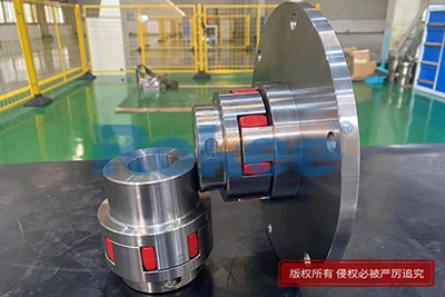
Several common structural configurations of flexible shaft couplers are widely used for motor shaft connections, each built to suit distinct motor types and working conditions. Jaw-style couplers feature two metal hubs with protruding interlocking teeth and a central elastomeric spider insert nested between the jaws. The motor shaft locks into one hub and the load shaft into the other, and torque transfers through compression of the spider insert. This design requires no lubrication, handles moderate misalignment, and is easy to disassemble for inspection or replacement of the flexible spider element, making it a frequent choice for standard motors driving pumps, fans, and general processing equipment. Beam-style couplers are one-piece cylindrical metal components with continuous spiral grooves cut along the body. The grooves create thin flexible ribs that bend to accommodate misalignment while maintaining zero backlash, a critical trait for stepper motors and servo motors requiring highly accurate position control. Oldham couplers consist of two hubs and a central sliding disc, which excel at handling larger parallel shaft offset and are often used for slower motor systems with significant radial displacement. Diaphragm couplers use stacked thin metal membrane plates fastened between hubs; they deliver high torsional stiffness and precise rotation at high speeds, fitting high-performance motor systems where angular accuracy matters most. Each configuration has practical limits. Jaw couplers lose precision once the spider begins to wear. Beam couplers cannot absorb heavy shock loads and risk fatigue fracture under repeated extreme misalignment. Understanding these structural differences helps match the coupler design to the motor’s speed range, torque output, motion profile, and alignment quality expected during long-term operation.
Installation practice heavily influences how well a flexible shaft coupler protects a motor shaft, and poor assembly can negate the benefits of flexible design. Before mounting the coupler, technicians must inspect both the motor shaft and mating load shaft surface for scratches, burrs, or corrosion, because surface defects can prevent secure clamping and create localized stress points that damage the shaft or coupler bore. The bores of the coupler hubs must match the diameter of the motor shaft and load shaft precisely; gaps or interference fits cause slippage or excessive clamping pressure that deforms the motor shaft surface. Clamping hardware, whether set screws or split clamp collars, must be tightened evenly according to consistent force levels. Over-tightening squeezes the hub bore and creates indentations on the motor shaft, weakening the shaft and complicating future disassembly. Under-tightening allows the hub to slip under torque loads, generating heat, scoring shaft surfaces, and causing unstable rotation. After securing both hubs, alignment checks assess angular, parallel, and axial offset. Even flexible couplers cannot compensate for extreme misalignment, and forcing operation beyond their designed displacement limits quickly wears flexible elements and transfers destructive loads back into motor bearings. Once alignment is complete, manual rotation of the assembly verifies free movement without binding or rubbing contact between coupler parts and surrounding machine structures. A short low-speed test run follows to check for unusual vibration or noise before bringing the motor to full operating speed. Careful installation reduces hidden stress, maximizes the coupler’s service life, and prevents avoidable damage to the motor shaft and bearings that often arises from rushed or careless assembly work.
Vibration and shock management represents one of the most valuable functions of flexible shaft couplers connected to motor shafts, directly improving the stability and reliability of motor-driven machinery. All electric motors produce a certain level of inherent vibration during rotation, originating from minor rotor imbalance, electromagnetic forces, and small variations in torque output. This vibration transfers through the shaft into connected equipment, and without damping, it resonates through the whole mechanical frame, amplifying noise and accelerating wear on bearings and fasteners. Flexible couplers with elastomeric internal elements dissipate vibrational energy through repeated small deformations, interrupting the path of vibration transmission between the motor and load. When the motor starts up or reverses rotation, sudden torque surges create mechanical shock. These transient impact forces can crack motor components, loosen mounting bolts, and damage gear assemblies. The flexible structure absorbs these sharp force spikes by stretching and compressing gradually, smoothing torque delivery so the motor does not experience abrupt resistance changes. Metal flexible couplers offer less damping but maintain consistent torsional stiffness for high-precision motion, where vibration suppression is secondary to positional accuracy. Operating conditions with frequent start-stop cycles or fluctuating load demand benefit most from elastomeric coupler designs because they reduce cyclic shock stress on the motor shaft. Controlling vibration also improves the consistency of process output in automated systems, reduces acoustic noise in working spaces, and lowers the frequency of maintenance checks required for loose fasteners and worn bearing surfaces.
The selection workflow for a flexible shaft coupler paired with a motor shaft requires evaluation of multiple interconnected operating parameters beyond simple shaft diameter matching. First, the continuous operating torque of the motor serves as a baseline, but selection must also account for peak torque events during startup, reversal, or sudden load spikes, which often exceed steady-state torque values. Operating speed is another critical factor, as high rotational speeds amplify the effects of imbalance and increase cyclic flexing rates on the coupler’s flexible components. Higher speed applications require careful consideration of material fatigue and dynamic balance of the assembled coupler. The expected types and magnitude of shaft misalignment must also be estimated, based on mounting method, thermal expansion rates, and the precision achievable during installation. If large parallel offset is expected, one coupler style may be preferred over designs optimized mainly for angular deviation. Environmental factors including ambient temperature, humidity, dust accumulation, and exposure to oils or chemical vapors influence material durability. Elastomeric materials degrade rapidly under high heat or harsh chemicals, while metal couplers withstand harsher thermal and chemical environments but lack damping performance. Motion characteristics also guide choices: systems requiring precise positioning and zero backlash lean toward solid metal flexible couplers, while equipment prioritizing shock isolation favors elastomeric types. The inertia added by the coupler mass should not be overlooked, especially for small servo and stepper motors, because excess inertia increases the load the motor must accelerate and decelerate. Balancing all these factors ensures the selected flexible coupler protects the motor shaft, delivers reliable torque transmission, and maintains stable performance across the full range of expected operating scenarios.
Regular inspection and maintenance routines extend the service life of flexible shaft couplers and prevent unexpected motor downtime caused by coupler failure. Visual inspection remains the primary method of routine assessment. For elastomeric coupler elements, operators look for surface cracking, permanent deformation, tearing, hardening, or softening of the flexible insert. Cracks often develop from repeated flex cycles or heat aging, and damaged inserts lose their ability to absorb misalignment and vibration. Metal flexible couplers require checks for fine fatigue cracks along the flexure grooves, corrosion, and loosening of clamping hardware. The clamping connections to the motor shaft need periodic verification, as vibration can slowly loosen set screws or clamp collars over time. Loose hubs create slippage that scores the motor shaft surface and creates unstable torque transfer. Noise and vibration changes during operation act as early warning signs. A noticeable rise in noise or vibration may indicate elastomer degradation, shifted shaft alignment, or loosening of coupler components. When inspection reveals wear beyond acceptable levels, timely replacement prevents secondary damage to the motor shaft and bearings. Maintenance work should happen during scheduled equipment shutdowns, with power to the motor fully isolated to prevent accidental startup. Cleaning the coupler assembly removes accumulated dust, oil residue, and debris, which can accelerate material aging and interfere with movement of flexible parts. Lubrication is not required for most flexible motor shaft couplers, unlike some heavy-duty coupling types, which reduces ongoing maintenance tasks. Consistent monitoring helps identify degradation at an early stage, avoiding catastrophic coupler failure that can seize the motor shaft or destroy connected machinery during operation.
Limitations of flexible shaft couplers for motor shafts are important to recognize, as their flexibility comes with practical trade-offs that define suitable and unsuitable operating scenarios. A flexible coupler can only compensate for misalignment within its designed working range. Severe shaft offset or angular tilt will overload the flexible element, causing rapid fatigue and transmitting heavy bending loads directly into the motor shaft and bearings. Users should not treat flexible couplers as a solution for poor mounting design or gross alignment errors. Elastomeric coupler materials experience gradual aging over time. Heat, ozone, oil exposure, and repeated flex cycles reduce elasticity, and performance slowly declines even under normal operating conditions. This means elastomeric inserts are consumable parts that require periodic replacement. Metal flexible couplers avoid elastomer aging but suffer from metal fatigue if operated continuously near their maximum misalignment limits, and they do not suppress vibration effectively. All flexible couplers introduce some amount of torsional windup under heavy torque, which can slightly reduce positioning accuracy. This torsional deflection is negligible in constant-speed transmission systems but may affect ultra-precise motion control applications if not accounted for during system design. High temperature environments restrict the use of elastomer-based couplers, as elevated heat softens polymers and reduces strength. Extremely low temperatures can make elastomers brittle and prone to cracking under impact. The maximum rotational speed of each coupler design is bounded by dynamic balance and material strength. Operating beyond rated speed risks structural failure. Recognizing these inherent constraints allows engineers to set realistic operating limits and avoid applying flexible coupler designs in situations where their weaknesses compromise motor system safety and performance.
The role of flexible shaft couplers continues to grow as motor technology advances across many mechanical systems, proving that this compact component remains a cornerstone of reliable rotary power transmission. Modern motor designs deliver higher dynamic response, tighter control loops, and more compact machine layouts, which place greater demands on shaft connection components. Smaller servo and stepper motors used in automation require lightweight, low-inertia flexible couplers with zero backlash to preserve motion accuracy, while large continuous-duty motors depend on robust elastomeric couplers to reduce shock and vibration in harsh industrial environments. As machine designs shrink mounting space between motor and load, coupler manufacturers refine compact form factors that maintain misalignment capacity within smaller dimensions. Improved polymer blends and precision machining techniques expand the operating envelope of flexible couplers, extending usable temperature ranges and resistance to chemical contaminants. Even with these advances, the fundamental purpose remains unchanged: to securely transmit torque from the motor shaft while shielding the motor from damaging forces caused by misalignment, shock, and vibration. Many equipment reliability programs focus heavily on motors and gearboxes yet overlook coupler health, which can become the weakest link in the power transmission path. Proper selection, careful installation, and routine inspection of flexible shaft couplers reduce unplanned downtime, cut repair costs, and preserve the operational integrity of electric motors. As mechanical systems evolve, the flexible shaft coupler will remain an essential interface between motor power output and driven machinery, balancing mechanical flexibility, torque capacity, and protective functions to support dependable motor operation across diverse industrial and automated applications.
Rokee is a professional manufacturer of industrial couplings in china, designing and customizing a wide range of drive shaft coupling products for customers worldwide. Submit your coupling drawings or technical specifications, and we can customize coupling products for you.
Coupling Categories




Links:
- Calibration Weight
- Digital Viscometer
- Carpas Industriales
- Exhibition Tent
- Industrial Cardan Shaft
- PU Sandwich Panel Machine
- PIR Sandwich Panel Line
- Sandwich Panel Machine
- Sandwich Panel Production Line
- PU Sandwich Panel Line
- Sandwich Panel Line
- Flexible Couplings Manufacturer In China
- Elastic Couplings Manufacturer In China